Traditionally, the turbocharger has been employed as a tool to boost engine power. However, more recently, the technology has been used to enable the downsizing of internal combustion engines (ICE), helping to improve fuel economy and reduce emissions, and therefore playing an important role in the global drive for Net Zero carbon emissions.
Turbochargers are complex, comprising of many precision components and one of the most fundamental are the sealing rings. Despite their small size, sealing rings play a crucial role in turbochargers, and their performance levels have a significant impact on the overall efficiency of the system. In fact, the consequences of sealing ring failures are not limited to power losses, but rather carry wider safety and environmental implications. Therefore, the design and performance of sealing rings has been receiving increasing levels of interest from industry professionals and academic researchers alike.
Essentially, sealing rings are used prevent liquid or gases from passing between two chambers or from leaking outside into the atmosphere. The different rings within a turbocharger help to reduce emissions in both these instances, by helping to improve the efficiency of the turbocharger, resulting in less fuel being used, and also by sealing the outer casing, preventing gasses escaping directly into the atmosphere. This article explains the basic function of the rings used to seal the different areas of a turbocharger.
Sealing the Centre Housing
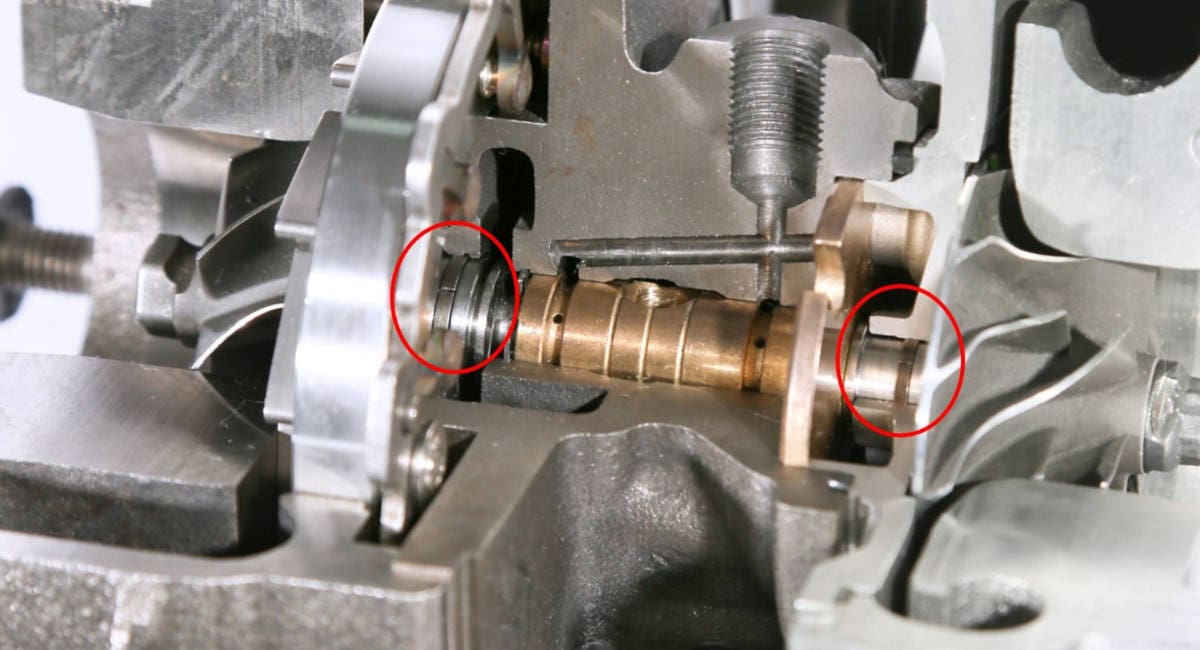
The Turbocharger centre housing, which contains the journal bearing, is sealed to prevent oil loss and against the hot exhaust gas in the turbine. One, or often two piston rings are fitted into precision machined grooves on the rotor shaft on both the turbine and compressor sides. These main shaft sealing rings do not rotate, but are held firmly in the centre housing. This contactless method of sealing is a form of labyrinth seal and the precision clearances create a near perfect seal that allows only a very small flow of exhaust gas to pass into the centre housing. This flow of gas also helps with keeping the oil contained within the centre housing.

Turbochargers with Wastegates
A turbocharger wastegate provides a means to control the boost pressure of the engine and protects the engine and the turbocharger by matching the power driving the turbine wheel to the power required for the boost. Typically, wastegates are incorporated into the turbine housing of the turbocharger (Internal wastegates) and require an external actuator with a crank shaft passing through the turbine housing to operate it, thus requiring reliable seals to prevent exhaust gases escaping into the atmosphere. Being part of the exhaust gas system, the actuator shaft seals needs to withstand very high temperatures and are therefore manufactured from superalloys.
Variable Geometry Turbochargers (VG, VGT, VNT)
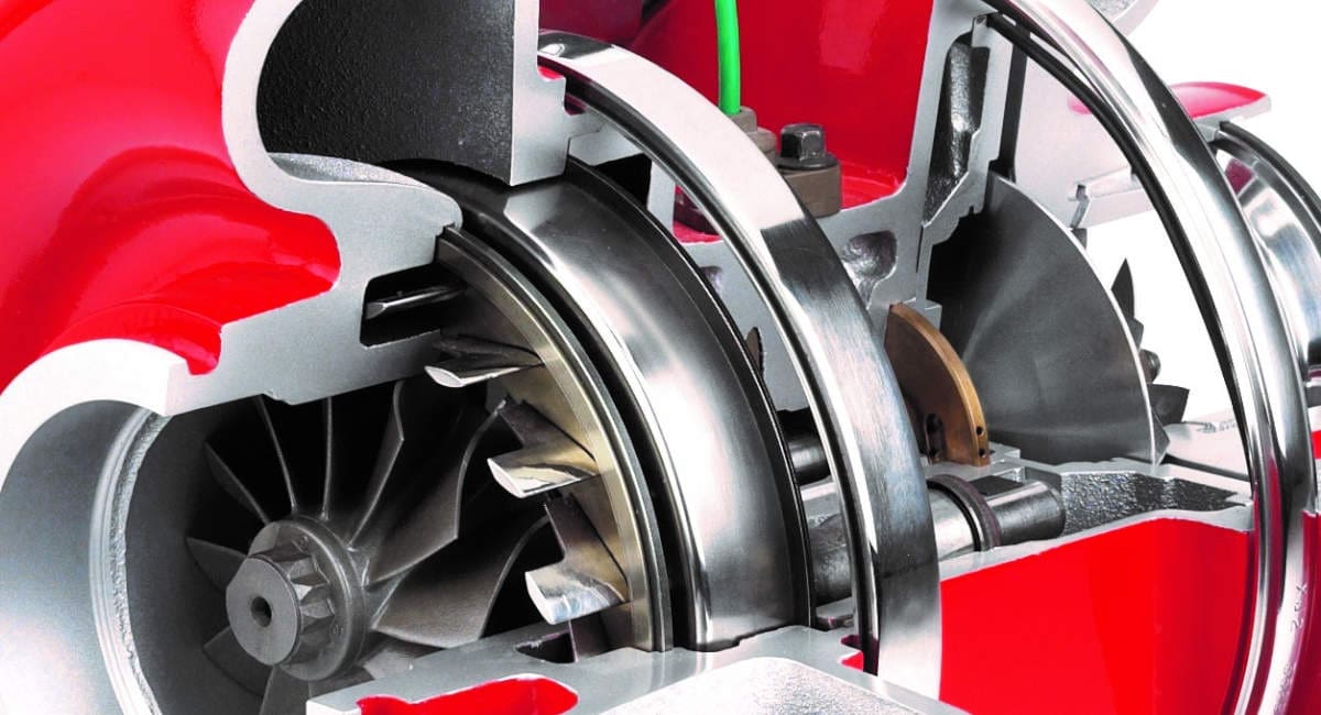
Variable geometry turbos have moveable vanes around the inlet nozzle of the turbine that adjust to vary the exhaust gas flow through the turbine wheel. Altering the geometry of the nozzle as the engine accelerates means the turbo’s aspect ratio can be maintained at its optimum level creating minimal turbo lag, a low boost threshold, and high efficiency at higher engine speeds.
The most conventional method of altering the geometry uses an external actuator to pivot the vanes. Similar to a wastegate actuator, this mechanism requires actuator shaft seals to prevent gases leaking from the turbine housing.
Another method is with axially sliding vanes. This method requires dynamic sealing with both in-springing rings sealing the outside diameter of a sliding nozzle ring, and smaller out-springing rings sealing the bore. This method is unique to Cummins Turbo Technologies’ Holset VGT™.

VG, VGT, VNT…. what does it all mean? Some of these acronyms are trademarks of a particular manufacturer but are more commonly used as a reference to variable geometry turbos in general:
- VGT—Variable Geometry Turbocharger (Cummins/Holset),
- VNT—Variable Nozzle Turbine (Honeywell/Garrett),
- VTG—Variable Turbine Geometry (BorgWarner and ABB)
- VG—Variable Geometry turbocharger (MHI)
- VGS—Variable Geometry System turbocharger (IHI)
- VTA—Variable Turbine Area (MAN Diesel & Turbo)
In some VGT designs, a nozzle shroud (or cage) is used to improve performance by directing all exhaust gas through the turbine wheel, and because it forms part of the inner exhaust gas casing around the turbine, upon refurbishment, it may be possible to replace the shroud rather than the a complete housing. Static joint rings are required to prevent gas leakage between the turbine housing and the nozzle shroud thus maintaining the desired performance level.
What’s the future for Turbocharger Technology?
The turbocharger’s role in reducing emissions from Internal Combustions Engines (ICE) is clear and turbo manufacturers are pushing the boundaries of the boosting system to achieve increasingly greater performance, reliability and efficiency from ICE and hybrid vehicles. New E-Turbo technology is further enabling engine downsizing due to improved performance and fuel economy.
With the phasing out of ICE vehicles, turbocharger technology continues to be at the forefront of developments in the global pursuit of Net Zero carbon emissions. Hydrogen fuel cells also need the compressed air that a turbocharger provides and so electric compressors, which use turbocharger principles, are being developed to supply the fuel cell system with oxygen, improving efficiency and also enabling downsizing of the fuel cell stacks together helping Fuel Cell Electric Vehicles (FCEVs) be a more viable part of the solution, alongside Battery Electric Vehicles (BEVs), for zero-emissions transportation needs.
If you have an application that requires sealing rings then get in contact with us today. We have a team of experts who can help and advice the best solution for you. Feel free to call us on +44 (0)3301 224 400 or email us at contact@crossmanufacturing.com. We look forward to hearing from you.
